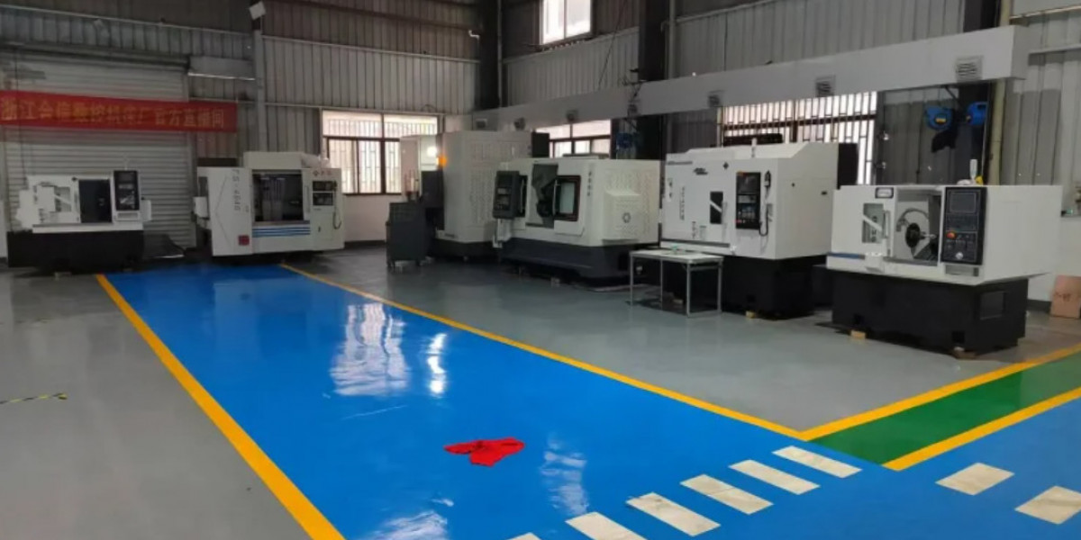

The processing of complex irregular-shaped parts often involves irregular contours, thin-walled structures, multi-faced transitions, etc. When using AI-powered CNC machining and data-driven methods, the cutting parameter settings need to go beyond the standard framework of common parts, dynamically optimizing based on process stages, workpiece rigidity, typeface characteristics, and material properties. The core is to balance processing efficiency, typeface accuracy, and deformation control.
For rough machining, the core is to remove the remaining material. However, the clamping rigidity of irregular-shaped parts varies greatly. For example, thin-walled irregular-shaped frames and slender irregular-shaped shafts. If conventional cutting parameters are simply copied, it is easy to cause vibration or deformation. During rough machining, priority should be given to controlling the uniformity of cutting load. Adopt a layered constant-height cutting mode to avoid sudden changes in cutting depth in a single process. In terms of parameters, the back-cutting allowance should match the local rigidity of the workpiece. For areas with strong rigidity (such as the protrusion area of the irregular contour), ap is set at 3-6mm, while for weakly rigid protrusions and thin-walled areas, it is reduced to 2-4mm; the feed per tooth fz is controlled at 0.12-0.22mm/z, which is 10%-15% lower than that of conventional parts of the same material, to avoid excessive chip buildup and vibration; the spindle speed is adjusted according to the tool material. When processing 45 steel with hard alloy tools, the rough machining spindle speed is set at 700-1100r/min, combined with high-pressure cooling to promote chip breaking and prevent damage to the typeface due to poor chip removal in the irregular curved surface.
In the semi-finish machining stage, the core is to homogenize the remaining material, laying the foundation for the finish machining. At this stage, the parameters need to be coordinated with the remaining material level of rough machining to reduce cutting force fluctuations. The back-cutting allowance ap is set at 1-2.5mm, which is more than 50% lower than that of rough machining; the feed fz is adjusted to 0.07-0.13mm/z, and the spindle speed is increased by 20%-30%, approximately 900-1500r/min, to weaken the surface hardening layer generated by rough machining and avoid uneven wear of the cutting tool during finish machining, which may cause deviation in typeface accuracy. At the same time, the semi-finish machining process uses constant linear speed control (G96 command) throughout. For each half radius of the irregular contour, ensure a constant cutting line speed to prevent uneven surface roughness due to sudden changes in line speed at concave and convex arcs. For example, at the transition R angle of the irregular surface, the feed rate is set to 80%, ensuring a smooth cutting path.
The parameters in the finish machining stage directly determine the typeface accuracy and surface quality of the irregular-shaped part. The parameters need to be stable. The back-cutting allowance is controlled at 0.2-0.5mm, only removing the small remaining material from the semi-finish machining; the feed fz is set at 0.02-0.08mm/z, with the rigid typeface section allowed to be slightly higher, while thin-walled and transition arc sections need to be reduced to within 0.05mm/z to avoid deformation caused by cutting force during assembly; the spindle speed is significantly increased, up to 2500-5000r/min when machining aluminum alloy irregular-shaped parts, and 1200-2200r/min for quenched steel irregular-shaped parts, combined with sharp finish machining coated tools to reduce size errors caused by tool wear. For the curvature transition areas of the irregular typeface, the feed needs to be reduced by 10%-15% to prevent over-cutting or vibration patterns. For example, at the transition R angle of the irregular surface, the feed rate is set to 80%, ensuring a smooth cutting path.
The underlying logic for parameter optimization needs to take into account both rigidity matching and dynamic adjustment: when the tool extension exceeds 3 times the diameter, the cutting parameters should be generally reduced by 15%-20%; when machining difficult-to-cut materials such as titanium alloys, the spindle speed should be reduced to 600-1000r/min to avoid high-temperature adhesion. In actual processing, it is necessary to first perform trial cutting at a strong-rigidity reference part, then fine-tune the parameters before applying them to the complex typeface, ultimately balancing efficiency and quality to meet the accuracy requirements of the irregular-shaped part.
AI powered CNC machiningdata driven https://www.hexincnclathe.com/ai-empowered-machining-from-experience-driven-to-data-driven-smart-manufacturing.html